


NXP France
All military and aerospace designs require more product functionality compared to previous generations. With such, there is pressure on manufacturing military-grade circuit boards and making them robust enough so that they comply with increasing functionality.
That demands or instead calls for the implementation of specific design and layout techniques. Some of them include designing such boards under an extra cushion of current, using the correct mil-spec materials, and keeping in mind stack up considerations, among others.
Let us look at 12 design tips that you need to pay attention to when designing military-grade circuit boards.
Military-Grade Circuit Boards Design Rules
Equipment that contains military-grade PCBs has to function faultlessly under harsh conditions. For this reason, their manufacturing process is identifiable by minimum tolerance and high precision. Several design rules must be adhered to when designing military-grade circuit boards. The layout, design, fabrication, and material selection need to follow stringent standards. Failure to follow such rules would bring about a malfunctioning board that would then affect the whole equipment’s functionality. Before you design a circuit board, you must have a plan in addition to doing and not doing it.

Military-Grade Circuit Electronic Components Performance
Unlike other types of PCBs, military-grade printed circuit boards are supposed to withstand thermal loads and maximum current to ensure reliability. Their design process must meet several standards aimed at ensuring their performance or functionality.
Some of the performance requirements that military-grade circuits have to meet are; FCC EMC standards, ISO 9001, and AS9100 standards, among others. The manufacture of safe, high-performing and reliable military-grade PCBs must follow some rules, an aspect that ensures useful functionality of military equipment even when under extreme conditions.
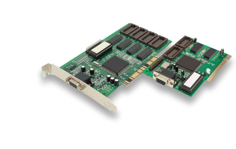
 circuit board. Computer motherboard. 3d illustration”/>
Military-Grade Parameters for Designing the Perfect PCB
Printed circuit boards meant for military equipment require detailed design compared to those involved for other applications such as the medical field or computers. For this reason, there are specific parameters intended for designing the perfect military-grade PCB.
Some of the most basic and essential design parameters aimed at developing the ideal PCB include factoring in crucial issues such as thickness, lamination, and the number of layers that a military-grade board must-have.
Another worthy parameter worthy of attention, especially when it comes to military-grade PCB is flammability. Military-grade PCBs should be somewhat resistant to burning and high temperatures.

Separation of Low-Frequency and High-Frequency Components
As mentioned earlier, designing military-grade PCBs is not an easy undertaking, as you may imagine. It requires precision and a lot of time to manufacture. For instance, power must not be kept together with ground planes when it comes to such designs.
Additionally, low-frequency components have to be apart or separate from high-frequency components.
If they are not kept separate, they may degrade the signal and bring about some noise, an aspect that is highly unacceptable in military-grade PCBs. When designing military-grade PCBs, manufacturers have to ensure that they separate low-frequency from high-frequency components.

Verify the Impedance Calculation
When it comes to printed circuit boards, the term ‘impedance’ is ubiquitous. Impedance is the sum of reactance and resistance of an electrical circuit measured in Ohms. The verification of impedance calculation is critical because it is somewhat challenging to test aerospace and military devices in a real environment.
There are several tools that one may use to verify impedance if need be. Impedance calculation will reveal as to whether there are some changes or alterations to the design that need attention.

PCB Trace Should Not Be More Than 45 Degrees
When designing military-grade circuits, designers need to ensure that the PCB trace routing is not higher than 45 degrees. It is also preferable to use curved traces. one of those essential design techniques that ensure that the transmission of current is smooth throughout the circuitry.
Trace angles that are of 90 degrees are forbidden based on the fact that the flow of current will hit the top of the 90- degree turn and go ahead to reflect backward. will then create a ripple effect that brings about an unclear signal.

Watch out for “Stacking” Issues During PCB Layout
When designing military-grade printed circuit boards, issues to do with stacking often come up. Designers need to watch out for stacking issues during PCB layout. Here, the rule of the thumb is to ensure the avoidance of fragile cores.
Additionally, designers need to keep at the back of their mind the type of material they choose to use in the internal layers of the board. Ideally, designers of military-grade printed circuit boards need to do away with two to three mil cores used as internal stack-up.

DFT is Essential
DFT, or Design for Testing is necessary. All the manufacture of military-grade printed circuit boards has to be in a way that it becomes easy to test them outside the system independently.
When it comes to military-grade printed circuit boards, testing is essential to ensure that the final product will always function reliably for many years to follow. Design for testing is helpful in the initial layout plan. A lack of a robust test process may see a manufacturing firm rolling out defective printed circuit boards that will later fail in the field.

Thermal Management
Thermal management involves the careful selection of components and materials that can withstand some of the most extreme heat and temperature conditions. For instance, metal-core printed circuit boards find substantial use in aerospace and military applications that generate significant heat and power.
When designing military-grade printed circuit boards, it is essential to factor thermal management issues by choosing some of the best materials and components that can withstand extreme heat and temperature conditions.
There are different types of materials, such as aluminum and epoxy-based materials that one can use. But when it comes to military-grade circuits, manufacturers need to go materials that can withstand extreme heat.

Reasonable Handling of RF Issues
RF interference takes place the moment some unwanted radio frequency signals go on to disrupt the use of specific equipment. Electrical equipment and transmitters are some of the most common causes of interference. When it comes to designing military-grade printed circuit boards, manufacturers must have in place mechanisms for handling RF issues.
To effectively handle RF issues, it’s essential to ensure that cables are short and have heavy gauge shields. Additionally, it’s important to double-check the connectors to verify quality signal and also install RFI filters along the signal path.

DFM Test
Military standards also call for more rigorous testing before the final production process. Apart from other types of tests, DFM, also referred to as Design for Manufacturability, is a must when designing military-grade printed circuit boards.
Even though this type of testing is a bit extensive, it is highly recommendable based on the fact that it ultimately brings about a superior product. Design for Manufacturability (DFM) is a test that looks at the underlying performance of the circuit board as well as other aspects such as variable humidity, thermal duress, and high electrical amperage, among others.

The use of Perfect Annular Rings
An annular ring is a technical term designated for the area between the conductive edge of the copper pad and the hole drilled into a via. Having in place messed up annular rings on the printed circuit board may ultimately affect the functionality of the PCB. To achieve perfect annular rings, manufacturers of military-grade PCBs ensure that they drill the holes effectively at the center of the via pad.
In reality, though, the accuracy and precision of the drilling depend on the machine that a manufacturer uses. When it comes to military-grade printed circuit boards, manufacturers need to ensure that there are enough annular rings on the board. Additionally, designers –especially those tasked with producing military-grade PCBs- can play a huge role in setting the best size on the design. Annular rings are ideal for military-grade PCBs, and it’s essential to ensure manufacturers get the right size.

Summary
For more than a decade, WellPCB has been providing high-quality, heat-resistant, and long-lasting printed circuit boards for a variety of defense and military applications.
WellPCB is ISO:9001:2008, RoHS, and UL certified. It means that you can rely on our printed circuit boards that can perform well, even under challenging conditions that are ideal for military equipment.
If you have defense and military applications that require quality printed circuit boards, WellPCB might turn out to be a wise and a very cost-effective option for you.
Unlike plenty of other printed circuit board manufacturers out there, we also do the assembly.
Explore our flexible PCB production services to find the best options for your application. At your earliest convenience, feel free to reach us for a free and also accurate quote regarding your order.