Placă de circuit personalizată
- Cum alegeți un PCB care să răspundă perfect nevoilor dvs. specifice?
- Acest ghid prietenos are tot ce aveți nevoie pentru a ști totul despre o placă de circuit personalizată
- Unde puteți obține cele mai bune plăci de circuite personalizate pentru nevoile dvs.
- Avem recenzori de standarde profesioniști care asigură măsuri stricte de control al calității în fiecare proces de producție.
- Folosim tehnologii avansate de testare, cum ar fi Test AOI , E-Test, X-RAY și controlul impedanței.
- Avem o analiză internă a procesului de proiectare și asamblare a PCB-ului, care asigură un control de înaltă calitate. Ne-am angajat să vă ajutăm să obțineți produse și servicii de cea mai înaltă calitate la prețuri competitive.
- Folosim o gamă largă de opțiuni pentru materiale PCB, cum ar fi FR4, High TG FR4, Rogers PCB, PCB pe bază de metal și materiale de înaltă frecvență.
- Avem un departament superior de asistență pentru clienți, care susține serviciile de la persoană la persoană. Departamentul nostru de asistență pentru clienți este flexibil și accesibil dacă doriți să faceți orice actualizări înainte de începerea procesului de producție.
Fabricare PCB
Capabilități
WellPCB este o companie de producție și asamblare a PCB-urilor cu renume și profesional, cu rădăcini în China. Tabelul de mai jos prezintă câteva dintre capacitățile primare pe care le oferim și le sprijinim. Conține informații despre materialele PCB pe care le folosim, tehnologiile PCB pe care le folosim, tipurile de produse pe care le fabricăm și toleranțele pe care le oferim.
-
Materiale:FR4, High TG FR4, Material fără halogen, CEM-3, Material Rogers HF
-
Toleranță minimă a conturului:+ / -0,1mm
-
Numărul de straturi:2-36 Straturi
-
Diametrul minim al găurii PTH:+ / -0,1mm
-
Thichness de cupru finalizat:0,5-5 OZ
-
Raportul maxim al grosimii / găurii bordului:12: 1
-
Grosimea panoului finalizat:0,2-6,0 mm
-
Min.Solder Mask Bridge:4mil (Min, SMT Pad Space 8mil)
-
Min.Line / Track Width:3mil
-
Min.Legend (Serigrafie) Lățimea pistei:5mil
-
MIN.Dimensiunea slotului de foraj:0,6 mm
-
Tratament de suprafață:HASL cu plumb, HASL fără plumb, aur de imersie, OSP, tablă de imersie, argint de imersiune etc.
-
Culoarea măștii de lipit:Verde, negru, albastru, alb, galben și mat etc.
-
Alte tehnologii:Deget auriu, mască peelabilă, Vias fără ochi, control al impedanței caracteristice, tablă flexibilă etc.
-
Duritate mască de lipit:6H
-
Culoare legendă / serigrafie:Negru, Alb, Galben și altele.
-
Înfășurați și răsuciți:≤0,7%
-
Inflamabilitate:94v-0
Procesul de fabricație a PCB-urilor
Folosim datele (fișier Gerber) pe care ni le trimiteți pentru a crea informațiile de producție pentru plăcile dvs. personalizate. Experții noștri potrivesc specificațiile dvs. cu capacitățile în scopul conformării.
Când realizăm placa de circuit, procesul de imagistică este ceea ce definește urmele circuitului. Procesul imagistic tradițional are nevoie de un instrument de lumină UV și fotografie pentru a transfera imagini. În același timp, LDI utilizează doar un fascicul laser controlat de computer, foarte concentrat pentru a defini direct modelul circuitului pe placă.
Aici, folosim procesul de gravare pentru a elimina orice reziduuri de cupru nedorite din panou. După îndepărtare, îndepărtăm pelicula uscată pentru a rămâne cu un circuit de cupru, care este în conformitate cu proiectarea PCB. Deci, practic, gravarea înseamnă îndepărtarea reziduurilor chimice și electronice nedorite.
Lorem ipsum dolor sit amet, consectetur adipiscing elit. Ut elit elit, luctus nec ullamcorper mattis, dapibus leo pulvinar.
Aplicăm un strat de oxid pe straturile interioare ale plăcii și apoi le stivuim împreună folosind prepreg pentru a crea izolație între ele. În plus, ar trebui să adăugăm folie de cupru la părțile superioare și inferioare ale stivei.
În acest pas, am alezat găurile care vor acționa ulterior ca contacte electrice în placa multistrat. Forarea este un proces mecanic pe care producătorii de PCB-uri îl optimizează pentru a obține înregistrarea la legăturile de strat intern. Este important să rețineți că putem face în continuare foraje cu laser. Avem o mașină de găurit cu laser, care poate găuri 3-6mil vias.
Mai întâi, aplicăm niște depuneri subțiri de strat de cupru pe găurile pe care le-am forat mai devreme pe pereți. PTH oferă cele mai bune depozite de cupru, care ascund pereții găurilor și întregul panou. Și acesta este un proces chimic pe care ar trebui să-l reglăm strict pentru a plasa depozite suficiente de cupru în pereții nemetalici. În al doilea rând, efectuați placarea panoului pentru a obține un depozit exterior de cupru mai gros.
Imaginea în strat exterior seamănă cu procesul de stratificare internă. Cu toate acestea, în forarea stratului exterior, scăpăm de pelicula uscată și menținem circuitele. Apoi plătiți cuprul suplimentar mai târziu într-un mediu curat.
Acesta este cel de-al doilea proces de placare electrolitică, unde efectuăm placări suplimentare în piese de film uscat (circuite). După depunerea cuprului, ar trebui să aplicăm staniu pentru a preveni oxidarea cuprului placat.
Mai întâi, scoatem filmul albastru uscat. În al doilea rând, răzuim toate reziduurile de cupru nedorite. Depozitele de staniu rezistă procesului de gravare, prin urmare, protejând depozitul de cupru dorit. În cele din urmă, am eliminat chimic reziduurile de staniu pentru a lăsa în urmă circuitele.
Cu ajutorul lucrărilor de artă și a luminii ultraviolete, expuneți câteva piese PCB și îndepărtați toate piesele expuse. Apoi vindecați complet masca de lipit rămasă pentru a crea un finisaj de calitate.
Finisarea suprafeței poate menține circuitele de cupru expuse, între timp, poate oferi o suprafață sudabilă atunci când lipiți componente pe PCB. De obicei, metalic și organic sunt cele două tipuri principale de finisaje de suprafață. Finisajul metalic al suprafeței include HASL, ENIG / ENEPIG, Argintul de imersiune, tablă de imersie, în timp ce finisajul de suprafață organic include OSP și Carbon Printing.
Vom testa toate plăcile înainte de expediere pentru a ne asigura că toate plăcile cu circuite imprimate nu prezintă defecte și îndeplinesc standardele pe care le așteptați. În prezent, avem două tipuri diferite de echipamente de testare disponibile pentru a testa plăcile de circuite. Unele mașini de testare includ o sondă de zbor, testere fără fixare. Și avem, de asemenea, capacitatea de testare a rețelei universale. Aceste mașini folosesc dispozitive construite special pentru PCB-ul dvs. Dacă aveți cerințe de control al impedanței, vom testa și valoarea impedanței cuponului.
Aici, direcționăm panourile de producție PCB în dimensiuni și forme particulare în conformitate cu fișierul de producție. PCB V-Scoring este un proces de tăiere a unei caneluri în formă de „V” în partea superioară și inferioară a unei plăci de circuite imprimate, lăsând un strat subțire între Vee. Odată ce am făcut acest lucru, poate separa cu ușurință placa PCB la V prin aplicarea unei presiuni minime.

În acest pas, o echipă de indivizi cu ochi ascuțiți examinează fiecare produs. Procesul implică examinarea vizuală a plăcii în conformitate cu standardele stabilite.
Ambalăm produsele dvs. învelindu-le cu grijă în materiale care îndeplinesc standardele internaționale de ambalare. Apoi le livrăm prin modul dvs. preferat de transport, în principal prin DHL, FedEx, UPS etc.
- Comenzi prototip plasate în 24 de ore
- Timp de plumb normal (5-7 zile lucrătoare pentru unele prototipuri PCB și producția de loturi mici)
- Timp de livrare mai rapid (48 de ore pentru unele prototipuri PCB și producția de loturi mici)
de ce noi
Din 2007, WellPCB a oferit PCB-uri de bună calitate, cu un timp excelent de livrare și satisfacție a clienților. Suntem unul dintre cei mai mari și mai calificați producători de plăci din China. Personalul nostru angajat – cu o bogată experiență în lumea electronică – produce produse superioare, cum ar fi PCB-uri pe două fețe, pe o singură față, multistrat și HDI.
Ansamblu PCB Quickturn
- Fabricarea PCB-urilor și achiziționarea pieselor se efectuează simultan, economisind timp
- Comenzi prototip plasate în 24 de ore
- Cotați și comandați Online în orice moment
Preț competitiv
- Prețul nostru este unul dintre cele mai competitive din lume
- Proprie fabrică cu control rezonabil al costurilor, fără costuri ascunse în ea
- Acceptați T / T, numerar, card de credit, PayPal, transfer bancar etc.
- Cele două fabrici ale noastre au suport pentru prețuri pentru comenzi diferite.
Livrare la timp
- Metodele standard sunt DHL și FedEx, servicii door-to-door. Timp mediu de expediere doar 2-4 zile.
- Colaborați cu două companii de transport timp de mulți ani cu prețuri reduse
- Anti-static + Umiditate + Anti-vibrații Ambalare ; Certificat de inspecție
- Agent profesional În Iran, Pakistan
Asigurarea calității
- Toate produsele respectă IPC sau Standardele UL și standardele ROHS și REACH.
- 98% evaluare pozitivă și satisfacție a clienților Managementul și procesele standardizate din fabrică Servicii de testare multiple
Returnare și rambursare
- În cazul în care PCB-ul nostru nu poate fi utilizat din vina noastră, puteți cere despăgubiri.
- Vă putem rambursa contul direct sau re-prelucra plăcile inutilizabile sau re-fabricăm PCB-ul și vă putem retrimite la costul nostru, dar vă rugăm să cooperați pentru a rezolva problema dacă trebuie să refaceți.
Scara fabrica PCB
Ne ocupăm de toate scările de producție, inclusiv comenzile de producție mici, medii și de masă.
În plus, putem livra lunar peste 10.000 de produse.
Avem prețuri competitive și oferte imbatabile pentru volume care variază de la 1 metru pătrat pentru dvs.
Certificările noastre
Iată certificatele pe care le avem:
IATF 16949: 2016 ISO 9001: 2015 ISO14001: 2015 ISO13485: 2016 UL De asemenea, toate produsele noastre respectă standardele IPC și ROHS. Mai important, ne străduim întotdeauna să producem produse PCB de ultimă generație.




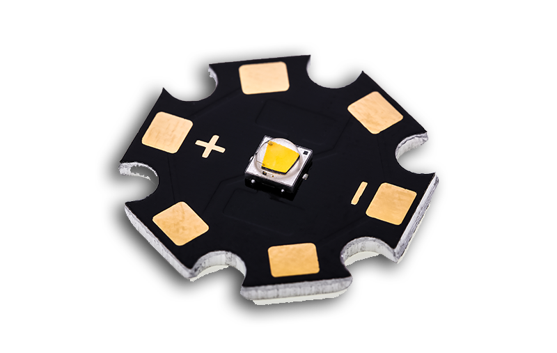
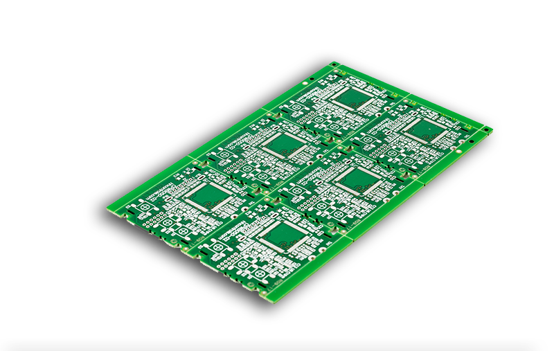
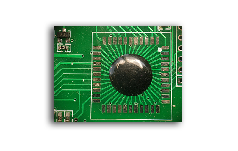
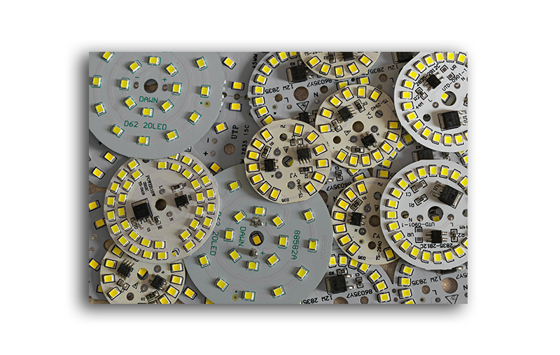
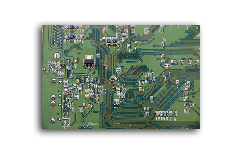
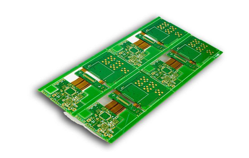
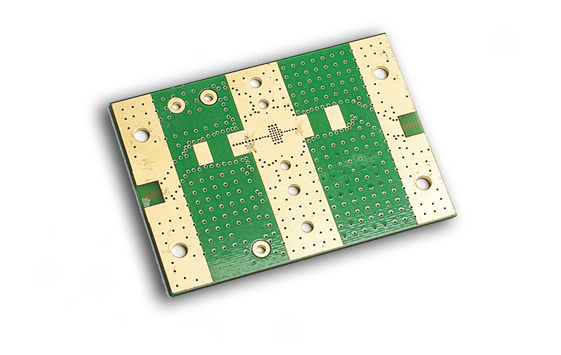
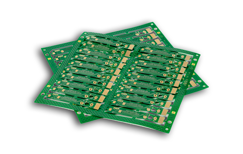
Salonul produselor PCB
Mărturie
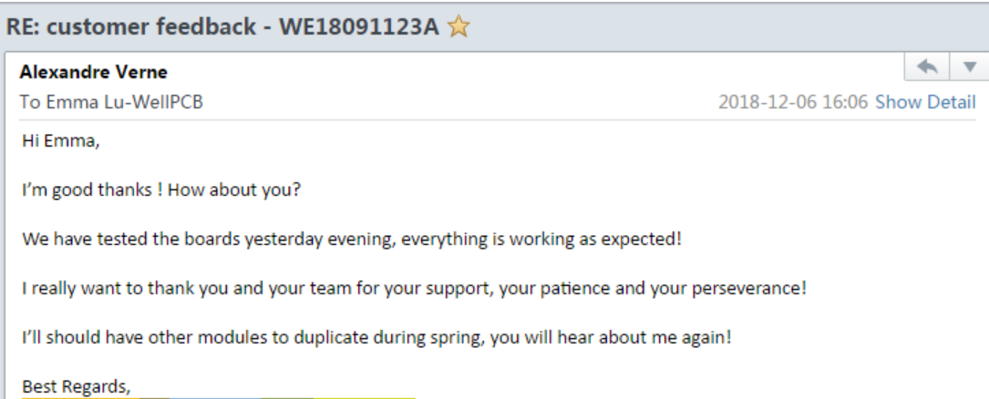
NXP France
Întrebări de top
1. What services do you offer?
We offer three primary PCB assembly services: PCB fabrication, consigned PCB assembly, and full turnkey services.
2. Is it possible to get stack-up drawings from you?
Yes, we are willing and ready to share some of our standard stack-up drawings with you, or even individual stack-up drawings that meet your specific requirements.
3. Do you offer any discounts?
Our two factories offer price support for various orders, especially for multilayer PCBs and mass production.
4. Can you view and process Altium CAD data directly?
Unfortunately no. We generally deal with Gerber files.
5. What if I am dissatisfied with PCBs from WELLPCB.com?
If you encounter any problem with our products or feel dissatisfied with our products or services, you can let us know through [email protected]. We promise to get back to you within 24 hours and serve you satisfactorily. We will either refabricate your PCB in case of a defect or refund the full amount without needing to return the defective PCBs. You may also choose to credit your[email protected] account and use the credit for future orders.
Circuit personalizat: Ghidul final pentru modul de proiectare
Every day, people depend heavily on electronic devices to get things done around the house and at their job places. These devices help us cook, clean, and do a host of other activities that would have been difficult or impossible to accomplish without them.
At the heart of every electronic is a printed circuit board (PCB). A PCB is a board that connects various electronic components in a particular device. So how do you choose a PCB that perfectly meets your specific needs?
This friendly guide has all you need to know everything about a custom circuit board, and where you can get the best custom circuit boards for your needs.
Table of Contents
Every day, people depend heavily on electronic devices to get things done around the house and at their job places. These devices help us cook, clean, and do a host of other activities that would have been difficult or impossible to accomplish without them.
At the heart of every electronic is a printed circuit board (PCB). A PCB is a board that connects various electronic components in a particular device. So how do you choose a PCB that perfectly meets your specific needs?
This friendly guide has all you need to know everything about a custom circuit board and where you can get the best custom circuit boards for your needs.
The Basics You Should Know About Custom Boards
1.1: PCB Prototype Board
In the first phase of developing a custom board. It is much simpler to use a board designed for prototyping. Keep in mind that the fabrication and design of PCB will be required when it comes to adding the final touches to the end product.
1.2: PCB Material
Some of the materials needed for creating a custom circuit board include the copper clad board as well as the positive photoresist. The copper gathers on a foundation that’s referred to as the substrate. Designers can choose between one and two layers of copper, depending on what type of board is in use. There’s a silkscreen that helps make the PCB readable. The substrate, usually known as FR4 (Fire Retardant), works as a thick foundation for the PCB. On top of the copper foil is a layer that’s referred to as the solder mask. It’s usually green in colour.
Some PCBs do not use these materials. Instead, they use epoxies, which have the disadvantage of being thermally sensitive.
1.3: PCB Types
PCBs come in many types, depending on the intended use. The most prevalent custom circuit boards include:
1. Single-sided printed circuit boards
2. Double-sided PCBs
3. Multilayer PCBs
4. Rigid PCBs
5. Flex PCBs
1.4: Printed Circuit Board Components
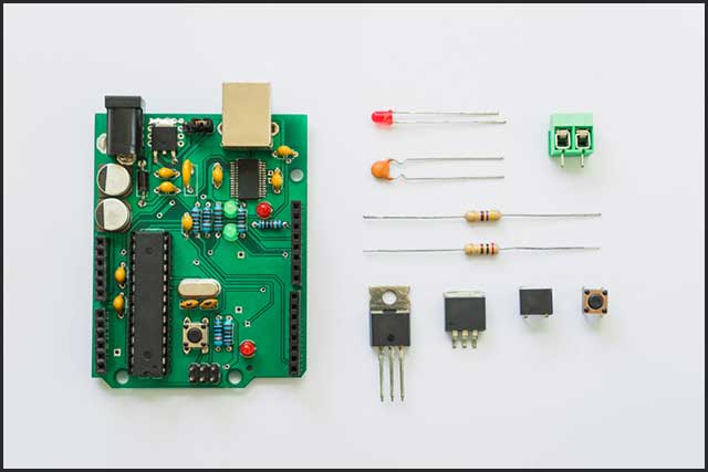
All electronic components, regardless of their function, have individual components that are essential for various circuits. These components include LEDs, resistors, battery, transistor, switch, diode, and inductor.
How is the Custom Circuit Board Designed?
2.1: The Design Basics
Before we get started on the basics of custom Circuit Board design, we need to get familiar with some terminologies. These include:
2.1.1 Schematic Capture
It is a program that allows the operator to create a schematic diagram of the electronic component as well as other features. In other words, it’s a graphical representation of the element.
2.1.2 Gerber Files
These are computer-aided design files. The files are sent to the custom circuit board producers to assist them in building the PCB structure.
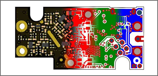
2.1.3 PCB Layout Tool
It is a program that allows for applying on multiple structures of the wiring connection structure. Once the construction is complete, the operator can then generate CAD files to be used to make the custom circuit board.
2.2: The Steps of PCB design
Different makers of printed circuit boards use different approaches when it comes to the designing of a custom circuit board. We’ve listed the essential steps below:
Step 1: Using of Software
Here, the designer chooses a suitable software to create a custom circuit board. One such software is EAGLE.
Step 2: Generating the Film
Using the finalized PCB diagram, the operator generates the film.
Step 3: Selecting Raw Materials
Where the intention is to design a simple device, the designer can use pocket-friendly material like paper phenolic that’s bonded with copper foil.
Step 4: The Drilling of Holes
Machines and drill bits help to drill holes at this stage. Both a hand machine and a CNC machine are applicable here.
Step 5: Fixing the Image
Here, the designer places a clean copper layer on the printer and stores the designed layout film on the computer before they print the command from the computer using a laser printer.
Step 6: Etching and Stripping
In this stage, the unwanted copper that’s attached to the custom circuit board is removed using different chemicals.
Step 7: Testing
It is the final stage, and it’s meant to ensure that the custom circuit board is fully functional.
Do You Know The Custom Circuit Board Software?
Currently, there’s a wide variety of software available in the market to help design custom circuit boards. Among the top software include: PCB Artist, Altium Designer 17, Ultiboard, DipTrace, SOLIDWORKS PCB, PCBWeb, BSch3V, Gerbv, XCircuit, Eagle PCBs, KiCad EDA, CircuitMaker, DesignSpark PCB, Pad2pad, ZenitPCB, OrCAD, CircuitStudio, PCB123, FreePCB and CUSPICE
3.1 Comparing Various PCB Design Programs
As you’ve seen, the list of software used for PCB design is long. We’ll pick two programs from the catalogue to compare. Of course, we can randomly select these two applications. Let’s take a look at DIPTrace and EAGLE CAD.
3.1.1 DipTrace
This software has many impressive capabilities. The program can perform schematic captures linked to the library. The software can also create patterns using a decent library editor. Users of this program can access tutorial and support. The software is also reasonably priced and has visually appealing colours. Generally, this software is ideal for small and simple custom circuit boards.
3.1.2 EAGLE CAD
This software is capable of electrical rule check, and forward and backward annotation between the PCB and schematic.
3.2. So what’s The Best Custom Circuit Board Design Software?
Given that there’s a great deal of circuit board design software in the market, putting your finger on the best among them is easier said than done. However, some design programs are highly recognizable due to their impressive functionality. One of them is EAGLE. This software is remarkably user-friendly and comes at a moderate price. The software can perform the batch execution of files as well as copper cladding.
Custom Circuit Board Layout Design
4.1: PCB Layout Design
The layout of a printed circuit board requires you to have some technical know-how and calls for the knowledge of software used to make PCB. You also need to be conversant with the computer-aided system used to make PCB, as well as have the skills required for the transfer of the basic PCB design to the final custom circuit board.
4.2: Comparing PCB Layout
When comparing various custom circuit board designs, we look at the following factors:
1. Board size
2. Layers available
3. Power delivery network
4. 3D modelling
5. Differential pair routing
4.3: PCB Layout Tutorial
Step 1: Converting the Schematic to a PCB
Once you have completed the schematics, click on “convert to PCB” on the specific editor you’re using. Doing so converts the schema to PCB.
Step 2: Dragging and Dropping the Component
Here, you place the document to the exact position you want it. If you prefer a neat looking custom circuit board, you can set the components that have a similar function next to each other.
Step 3: Sketch a Custom Outline
Here, you need to go to the layer menu and select the board outline layer. Then you click on the outline and delete it. Next, create your preferred shape using the printed circuit board tools.
Step 4: Copper Area
This step involves joining different parts to one signal. You can create a copper area with the tools menu.
Step 5: Routing
There are two ways to complete the route. Where there’s low current where you’re creating the custom circuit board, use the auto-router function at the top of the page to do it. Where there’s the need for different track sizes, it’s best to do routing manually.
Step 6: Holes
Irrespective of what you’re designing a custom circuit board for, you’ll still need to mount it on something. To create holes on the PCB for this function, use the Hole tool on the tools menu.
Step 7: Adding Pictures and Text
To add pictures and text onto the PCB, go to the tools menu, and stroll to find the text or picture tool. Position your preferred book or make changes as you wish.
Step 8: Photo View
As soon as you’re through with the above steps, it’s the time to view the result. In case you’re not happy with the colour or some other feature, you can change it. If you’re satisfied with the final result, click on “fabrication output.” That helps you buy the custom circuit board.
Printed Circuit Board Reverse Engineering
Sometimes, the schematic is not available. In such cases, you can produce replacement parts using the data created from the PCB reverse engineering. Reverse engineering a custom circuit board can be a tedious and challenging; process, but it still has to be done at times.
5.1 Why We Reverse Engineer PCBs
So why would we bother to reverse engineer circuit boards, given the time and effort involved? Well, here are just some of the principal reasons:
- To replace components on the PCB that have become obsolete
- Reposition some of the board components
- To improve the functionality of the circuit board
- Analyze and enhance security requirements
Conclusion
Given the enormous role that printed circuit boards play in electronic devices, the PCB you choose must be ideal for your needs. At the beginning of this article, we’ll tell you what’s involved in creating a custom board. I hope this information will help you. We also promised we’d help you find the right vendor for you. That’s where WellPCB comes in. When it comes to reliable, cost-effective, and durable products, you can count on us every time. Our PCB solutions are customized to fit your unique needs.
Would you like to discover more about our high-quality products? One call is all it takes! We have the best, and it’s all for just you.

Hommer
Hi, I am Hommer, the founder of WellPCB. So far we have more than 4,000 customers worldwide. Any questions you can feel free to contact me. Thanks in advance.